Measuring Fully Modulated Carrier Power
Now let's consider what happens when we 100% or "fully" modulate the carrier.
What does it mean to "modulate" the carrier? When you key the mic a dead (unmodulated) carrier is created and transmitted. As the name implies, the carrier's job is to "carry" the information through the air from transmitter to receiver. The carrier is useless until it's modulated by some type of audio frequency information. Your voice is the audio information that usually modulates the carrier.
A problem crops up when we try to use a human voice for RF power measurement purposes. The human voice is made up of many different audio frequency tones, and it is also dynamic (ever changing). To measure RF power we need to use a single, continuous tone so that our measurements are accurate and consistent. To do that we use a device that produces a single, pure (sinusoidal) audio frequency signal. The frequency of that signal is usually 1000 Hz (cycles per second).
In a pinch, the human voice can be used to produce a fairly steady and continuous tone. Whistling, humming, or holding the first syllable of a word like "audio" into a mic while taking a measurement will work when nothing better is available.
A better method is to build a simple, low-cost audio frequency signal generator. There are many simple circuits to be found in basic electronics texts. Many use the common 555 timer IC. Although the signal generated by most of them isn't a pure sinewave, they can still be very useful for making RF power measurements. The load used in most of these circuits is a small speaker. A mic can be held near the speaker to inject the tone into the radio thus modulating the carrier.
The ideal way to modulate the carrier for test purposes is to use an audio signal generator that produces a pure 1000 cycle sinewave. A good way to inject the 1000 cycle tone into the radio is to use a spare mic plug with short (one inch) wires soldered to it's pins. The audio signal generator should be equipped with a shielded cable that ends in small test clips. The test clips are attached to the proper wires on the mic plug. A switch with wires and test clips is then connected to the proper wires on the mic plug so that the radio can be switched between the transmit and receive modes. When you're ready to make a measurement you simply switch the radio into the transmit mode and set the mic gain and the output of the generator to inject as large a signal as is necessary.
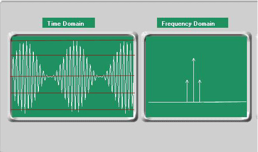
Above is a graphic shows a 27 MHz carrier that's being 100% modulated by a pure 1000 cycle tone on both an oscilloscope and a spectrum analyzer. Both are still set up the same way as when the dead carrier measurement was taken.
You'll notice that on the scope the amplitude (size) of the signal gets bigger and smaller at the same time. That's modulation. The audio signal that we injected is manipulating (modulating) the carrier. At the 100% modulation point the carrier, at times, is twice as big as it was when it was unmodulated, and at other times it's almost completely reduced to zero. That's how you can tell that the modulation percentage is 100%.
Something to remember here is that the signal is "symmetrical." In other words, the positive modulation swings (which make the carrier bigger than it was when it was unmodulated) and the negative modulation swings (which make the carrier smaller than it was when it was unmodulated) are equal and opposite. In a textbook amplitude modulated signal the modulation swings are ALWAYS equal and opposite (symmetrical). That's important to remember because UNsymmetrical modulation is very common in CB transmitters. We'll be discussing that in more detail later.
On the spectrum analyzer you'll notice that two more spikes have come up. Those represent the actual information that's being transmitted. In this case the information is a 1000 cycle tone. You'll notice that on the spectrum analyzer the carrier power didn't change at all. The new spikes are separate and distinct. The reason they are separate and distinct is because they make up what are called the "sidebands."
Now is a good time to explain what an A.M. signal is made up of. There are three parts that make up the "composite" A.M. signal: the carrier, the upper sideband, and the lower sideband. You can see those three parts on the spectrum analyzer display. The information in an A.M. signal is contained in the sidebands. The carrier contains no information. Both sidebands are mirror images of each other and contain the same information. That's why single sideband transmission and reception is possible. The carrier and one of the sidebands can be suppressed to the point of virtual non-existence, yet the remaining sideband will still convey all the information contained in the composite A.M. signal.
Now, getting back to our A.M. signal, we can make another peak envelope voltage measurement and convert it to a peak envelope power measurement.
Remember our conversion equation:
![]()
40 times .707 equals 28.28.
28.28 squared equals 799.7584.
799.7584 divided by 50 equals 15.995168; which can be rounded up to 16.
You'll notice that the peak envelope voltage doubled, and that the peak envelope power quadrupled. At 100% modulation our transmitter is producing 16 peak watts at the crest of the positive modulation swings .
Something else you may have noticed is that the peak wattage could also work out to be zero if you were to measure the peak envelope power at the negative modulation peaks (where the carrier voltage is zero). That's why there are other types of power measurements like average and RMS. We'll discuss those measurements later.
Next, we'll be considering an overmodulated (in excess of 100% modulated) signal and discussing the pros and cons of purposely overmodulating.