This tutorial is designed to help explain some of the concepts involved in RF power measurement for amplitute modulated signals.
Measuring The Unmodulated (Dead) Carrier Power
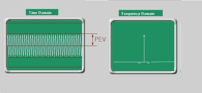
Okay, let's get started. The graphic above is of an unmodulated (or dead) 27 MHz carrier as displayed on an oscilloscope (time domain) and a spectrum analyzer (frequency domain). An unmodulated carrier will look like a white band when the scope is set to sweep at the rate required to see the much lower frequency audio signal that modulates the carrier. It will look like a sine wave when the sweep rate is increased to the point where the scope will trigger on the fundamental 27 MHz signal; this requires a scope with a vertical bandwidth of at least 35 MHz (with 50 MHz or more being preferable). Since the unmodulated 27 MHz signal is relatively pure (clean), the spectrum analyzer is displaying a single 27 MHz spike. If the signal wasn't clean there would be smaller spikes at other frequencies on either side of the main (fundamental) spike.
An oscilloscope is basically a voltmeter that can also give you information on the shape and quality of a signal (aka waveform). It's probably the best all-around tool for measuring the quality and amplitude (power) of a CB transmitter's output signal. To use a scope for that purpose use a 10X probe so you don't load down the circuit. You'll also want to use a dummy load rather than an antenna for two reasons: so that you'll know what the actual circuit resistance is for use in the power (wattage) formula you're about to be introduced to; and so that your measurements are not skewed by the presence of harmonic and parasitic components that might otherwise be displayed on the scope along with the fundamental signal. The easiest place to pick your signal sample off of is the antenna connector center pin inside the radio (or amplifier). Make sure your probe has a ground lead and that you've attached it to the chassis near the antenna connector. Also, before making any measurements, make sure the probe and the scope are properly adjusted and calibrated. It's beyond the scope of this tutorial to get into proper scope useage. There are many good sources for that information. Here are a couple of links that might be helpful: scope fundamentals-and- probe selection.
Now that we know how to take an accurate RF (radio frequency) voltage measurement using an oscilloscope, we need to convert the voltage measurement into a wattage measurement for it to mean anything. We use a fairly simple mathmatic equation to do that. Here's an explanation of that equation:
Peak Envelope Power (PEP) is defined as:
![]()
PEV = Peak Envelope Voltage = the voltage from the center line on the scope to the highest point on the waveform.
R = dummy load resistance.
PEP = Peak Envelope Power (in watts).
The calculations for a stock CB would go something like this...
![]()
This means that the above virtual scope is using a 10X probe and is calibrated to display 2 volts per division.
Let's work this equation manually just to make sure it's fully understood:
What we want is the wattage. We know what the dummy load resistance is (50 ohms), and we know what the peak envelope voltage is (20 volts). Now, all we have to do is work the 3 steps of the equation:
1. The peak envelope voltage (20) times .707 equals 14.14.
2. 14.14 squared (14.14 times 14.14) equals 199.9396.
3. 199.9396 divided by the dummy load resistance (50) equals 3.998792 watts; which is close enough that it can be rounded up to 4.
That's pretty slick isn't it?
Something you may have noticed is that in this case the PEP is equal to the RMS or average wattage figures you may have seen in CB radio advertising and/or specifications literature. This often causes confusion and will be explained in greater detail later.
Don't go on to the next section unless you COMPLETELY understand what's been explained here. The next sections assume that you understand what's been covered here and will build upon it. The next sections won't do you any good unless you understand the material presented so far.