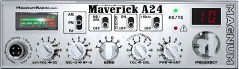
Magnum Maverick A24
Documentation Project

CBTricks.com

TIPS:
You need to have Acrobat Reader version 5 or newer installed to view the files with icon.

If the files with or icon will not display see the Site FAQ for help on printing and using this information.


RADIO MODIFICATIONS
      Frequency Conversion and Echo Modification

ALIGNMENT�PROCEDURES���
     PLL Alignment
     Transmitter Alignment
     Receiver Alignment
     Alignment Locations

DIAGRAMS
    A24 Schematic Diagram

PCB Layouts and Parts
    Main PCB Layout
    Main PCB Scan of the bottom
    Channel Selector and Display PCB's (Parts Layout)
    Channel Selector and Display PCB's (Trace Layout)
    ECHO PCB Layout (Parts Layout)
    ECHO PCB Layout (Trace Layout)

Also See:
RF Limited / Magnum Tech Notes Section

Mic Wiring

Stock
1-Shield
2-Audio
3-Transmit
4-Receive

Astatic
1-Shield & Blue
2-White
3-Red
4-Black
Yellow NC

Turner
1-Shield & Red
2-White
3-Blue
4-Black
Yellow NC

Sadelta
1-Shield
2-White
3-Brown
4-Green


Copyright © 1998, 1999, 2000, 2001, 2002, 2003, 2004, 2005 CBTricks.com

Disclaimer: Although the greatest care has been taken while compiling these documents,

we cannot guarantee that the instructions will work on every radio presented.