 |
RADIO
MODIFICATIONS
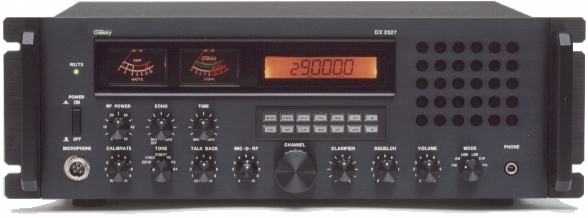
DX2527
Frequency Conversion
Clarifier
Mod
ALIGNMENT
PROCEDURES
PLL Alignment
Transmitter Alignment
Receiver Alignment
SEMICONDUCTOR
INFORMATION
Transistors
Voltage Chart (This is still being worked on)
Integrated Circuits Voltage Chart
Semiconductor
Datasheets
DIAGRAMS
DX2527
Schematic Diagram (old) (Nov. 07, 1998)
DX2527
Schematic Diagram (new)
(May 07, 1999)
DX2527
CPU PCB Schematic (DPT295042Z)
(Aug. 16, 1997)
DX2527
ECHO / ROBOT PCB Schematic (EPT0SSB50C)
Power
Supply Schematic Diagram
DX2527
Inter-connection Diagram
DX2527
Inter-connection Diagram 
PCB Layouts and
Parts
Main PCB Layout
(EPT295013Z)
Push Button PCB
(EPT295031Z)
Power
Supply PCB (EPT0SSB61A) Used in Early Production Radios
Power
Supply PCB (EPT0SSB62A) Current Production
Power
Input PCB(EPT0SSB91Z)
Channel
Selector PCB (EPT295090A)
Clarifier,
Squelch, Vol. VR PCB (EPTSSB130A)
RF
Power, ECHO, TIME VR PCB (EPTSSB120A)
Calibrate
VR PCB (EPTSSB150A)
LED
PCB (EPT0SSB20A)
EAR
Jack PCB (EPTSSB180A)
MOD
Meter PCB (EPT00GR60Z)
SWR
PCB (EPT360041Z)
ROBOT
/ ECHO PCB (EPT0SSB50C)
CPU
P.C.B. (DPT295042Z)
MIC
JACK PCB (EPT295070Z)
MODE
Switch PCB (EPT295090Z)
Stock
Mic Wiring Diagram
|
Mic Wiring
1. Ground Shield
2. Audio Yellow
3. Transmit Red
4. Receive Black
5. CH. Up White
6. CH. Down Blue
TURNER 4-WIRE
MIC. WIRING
1. Ground Shield
2. Audio White
3. Transmit Black
4. Receive N/C
5. CH. UP N/C
6. CH. Down N/C
TURNER 6-WIRE
MIC. WIRING
1. Ground Shield & Red
2. Audio White
3. Transmit Blue
4. Receive N/C
5. CH. UP N/C
6. CH. Down N/C
ASTATIC 4-WIRE
MIC. WIRING
1. Ground Shield
2. Audio White
3. Transmit Red
4. Receive N/C
5. CH. UP N/C
6. CH. Down N/C
ASTATIC 6-WIRE
MIC. WIRING
1. Ground Shield & Blue
2. Audio White
3. Transmit Red
4. Receive N/C
5. CH. UP N/C
6. CH. Down N/C
|