Uniden
PC122
Documentation
Project
CBTricks.com
|
TIPS: If the files with
|
|
 |
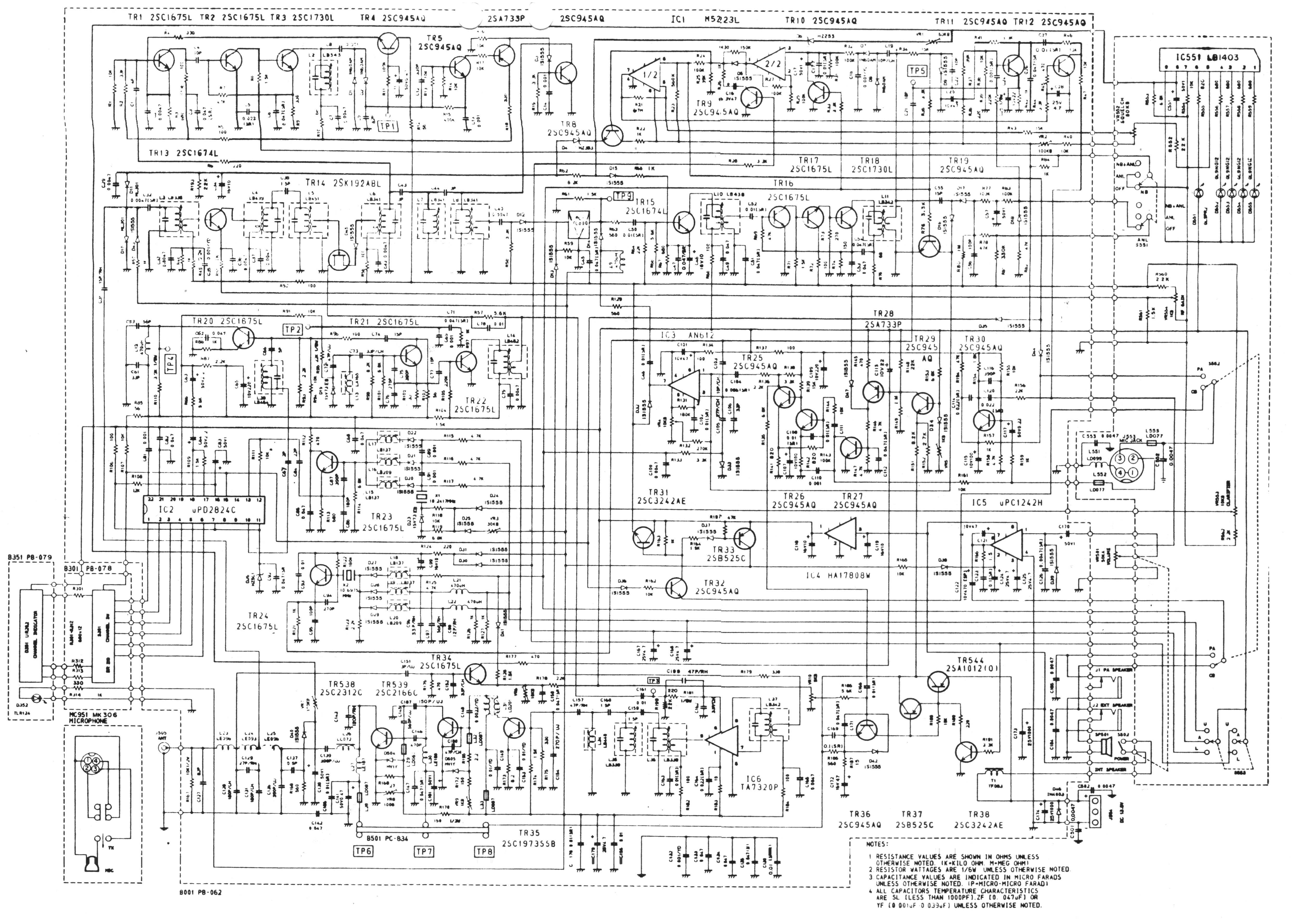
Diagrams
(All I had was a copy of a copy so these scans are not that good I will
re-scan when I find a better copy of the schematic) Alignment
(Courtesy
of David at DTB Radio) |
|
Disclaimer: Although the greatest care has been taken while compiling these documents,
we cannot guarantee that the instructions will work on every radio presented.