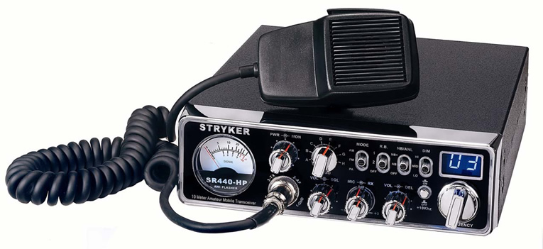
Stryker SR-440HP
Documentation Project

CBTricks.com

TIPS:
You need to have Acrobat Reader version 5 or newer installed to view the files with icon.

If the files with or icon will not display see the Site FAQ for help on printing and using this information.


Click to See Closeup

Picture Tour of Radio

Owner's Manual

ALIGNMENT PROCEDURES
     Alignment

RADIO MODIFICATIONS
      Frequency Mod
      Channel Chart

DIAGRAMS
      Schematic Diagram
      Schematic Diagram (Updated 07/09/08)


PCB Layouts
    Main PCB (PCBX-9821R20)
    Final Power Amp PCB (PCBX-0421R2)
    CPU Channel Sel. PCB (PCBX-0510R1)
    Front Panel Black Lite PCB (Top) (PCBX-0520R1)
    Front Panel Black Lite PCB (Bottom) (PCBX-0521)
    Rotary Switch PCB (PCBX-0322)
    Slide Switch PCB (PCBX-0506R1)
    MIC PCB (PCBX-9709)
    Echo Talkback PCB (PCBX-0319R4)
    SWR Power Shutdown PCB (PCBX-0309R2)

Datasheet for the LED's used in the Front Panel

Note: It is recommend not to disable or remove the modulation limiting circuitry.

UPDATE 04-12-2006
All new SR-440HP radios using the M1104 will be configured so you can use the SD1446 as a drop in replacement. This includes the next shipment of radios which will arrive in mid April. These radios will be easily identified because the heat sink will be drilled to accept transistors with both case or mounting styles.
This should eliminate ANY concern regarding the transistor used because the SD1446 is very easy to source.


Mic Wiring

Stock
1-Shield  (ground)
2-Yellow (audio)
3-Red     (transmit)
4-White  (receive)

Astatic
1-Shield & Blue
2-White
3-Red
4-Black
Yellow NC

Turner
1-Shield & Red
2-White
3-Blue
4-Black
Yellow NC

Sadelta
1-Shield
2-White
3-Brown
4-Green


Copyright © 1998, 1999, 2000, 2001, 2002, 2003, 2004, 2005 CBTricks.com

Disclaimer: Although the greatest care has been taken while compiling these documents,

we cannot guarantee that the instructions will work on every radio presented.