| 9. | On the solder side of the main PCB, locate the junction of L-107 and R-196. If there is a 1N4148 diode soldered to this junction, remove it. If there is no diode soldered to this junction proceed to step 10. |

Magnum
Delta Force
Documentation Project
CBTricks.com
Magnum DeltaForce Receiver Enhancement
Modification Instructions: (Before doing this mod please read the Mod update for RFlimited)
|
This enhancement increases the receiver's ability to deal with large energy RF signals both on and off frequency. A kit of parts to perform this enhancement is available at no charge to all DeltaForce owners. Contact Magnum International toll free at 1- 877-MAGNUM-9 (1-877-624-6869) with your DeltaForce serial number to receive your free parts kit. IMPORTANT NOTICE: If this receiver enhancement is being installed in a brand new unsold DeltaForce please test the radio thoroughly before doing any work on the radio. Please check all transmit and receive functions and all features to make sure they are working properly If a problem is found please call 1-877-MAGNUM-9 for warranty return instructions. It is important to test all functions before working on the radio to keep the factory warranty in place. |
| 1. | Locate
FL102, near the SSB XTAL filter. If FL102 is a 10.7MHz ceramic filter
then go to step 3. If FL102 is a metal can, MCF (monolithic crystal filter), then it must be replaced with a 10.7MHz ceramic filter, proceed to step 2. Note: Less than 5% of all DeltaForce radios have an MCF installed, most radios already have a 10.7MHz ceramic filter installed. If the radio you are going to modify has an MCF at FL102, contact Magnum at 1-877-MAGNUM-9 for a 10.7MHz ceramic filter free of charge. |
| 2. | Unsolder the MCF at FL102 and install a 10.7MHz ceramic filter. When replacing the MCF take note if the MCF's metal can is soldered to L-112. If so, there is a cut trace and a resistor inside a yellow sleeve on the solder side of the PCB at FL102. When unsoldering the MCF, remove this resistor and use a jumper wire to reconnect the cut trace after you have installed the 10.7MHz ceramic filter. |
| 3. | Remove
Q-126 (2SK163) and replace with J-310. Note that the J-310 does not have
the same polarity pin out as the 2SK163. The J-310 included in the kit
has 1 lead bent and redirected. Install the J-310 so it is reverse to the TO-92 symbol screened on the PCB. Confirm correct placement by observing the bent lead is inserted in the hole that connects to L-109. |
| 4. | Remove R-201 and replace with 1.8K ohm resistor. |
| 5. | Remove Q-124 (2SC3355) and replace with 2N3563. The 2SC3355 and the 2N3563 have the exact same pin out. Install the 2N3563 following the TO-92 symbol on the PCB. |
| 6. | Vertically install a 2K ohm resistor at R-193. |
| 7. | Remove the 22 ohm resistor at SJ-6 or R-390 (depending on which generation radio you have) and replace it with jumper. |
| 8. | Locate D-109. If D-109 is a germanium diode, replace it with a 1N4148 silicon diode. If D-109 is already a silicon diode, then proceed to step 9. |
| 9. | On the solder side of the main PCB, locate the junction of L-107 and R-196. If there is a 1N4148 diode soldered to this junction, remove it. If there is no diode soldered to this junction proceed to step 10. |

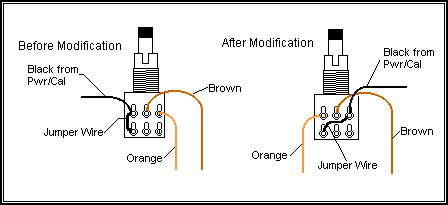
| 10. | Rewire
RF gain potentiometer. See diagrams. NOTE: This step is for cosmetic purposes only Rewiring the RF gain pot is not necessary from a performance standpoint. If you decide to skip this step the rotation of the RF gain control will function in reverse. For example, the maximum RF gain setting will be full counter-clockwise instead of full clockwise. a) Remove the knobs from the RF Gain / MIC Gain potentiometer. b) Using long needle-noise pliers, loosen and remove the mounting nut from the potentiometer. c) Carefully slide the potentiometer out of the front panel so that the pins are easily accessible. d) Move orange wire from pin 1 to pin 3. e) Move jumper wire from pin 6 and 3 to pin 6 and 1. |
| 11. | Several variable inductors need to be retuned. A signal generator is required to proceed. |
| 12. | Set signal generator to AM. |
| 13. | Adjust L-106 and L-107 (located on each side of 2N3563) to maximum signal. |
| 14. | Adjust L-108 to maximum signal. |
| 15. | Adjust L-109 to maximum signal. |
| 16. | Adjust AM inductors, first L-102 and then L-103, for maximum signal. L-102 and L-103 are located near the center of the PCB and are the only cans with blue painted adjustment slugs. |
| 17. | Readjusted L-106 and L107 (repeat step 13). |
| 18. | Enhancement completed. Turn on and test transceiver. |
PARTS LIST
|
Qty
|
Part | Description |
|
1
|
J310 | FET Transistor |
|
1
|
2N3563 | Si Transistor |
|
1
|
2.0K Ohm | Resistor (Red-Blk-Red) |
|
1
|
1.8k Ohm | Resistor (Brn-Gry-Red) |
|
1
|
1N4148 | Diode |
| NOTE: The above parts list is necessary to complete this receiver enhancement modification. If you do not have these parts, you may contact Magnum International with your DeltaForce serial number to receive a free parts kit. |
Copyright© 2000 Magnum
International
Ammended by www.cbtricks.com
Used by permission