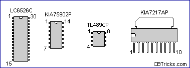
Realisitic
TRC-476
Documentation Project
CBTricks.com
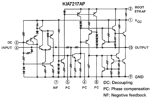
Integrated Circuits Internal
Diagrams

 |
 |
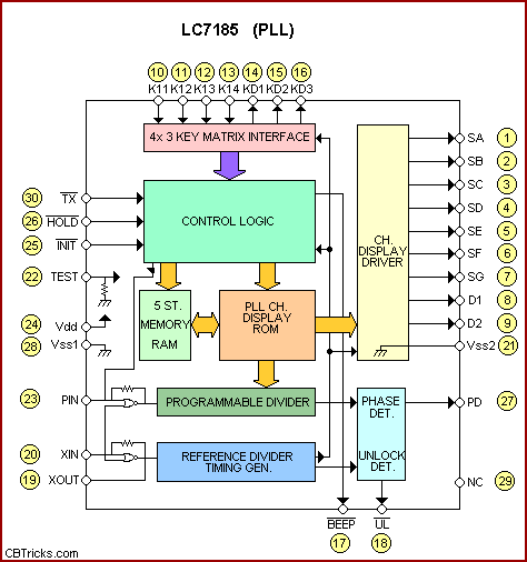
Pin Descriptions
| TX: Transmot/receive select | PD: Charge pump output |
| HOLD: Hold mode select | NC: Non connection |
| INIT: Reset Line | SA to SG: Segment drivers for display |
| TEST: Test point (input) | D1, D2: Digit output for display |
| Vdd,Vss1,Vss2: Power supply | K11 to K14: Key input |
| PIN: Programmable divider input | KD1 to KD3: Key scan outputs |
| XIN,XOUT: Crystal oscillator input, output (e.g. 10.240MHz | BEEP: Beep-tone control output |
| UL: Unlock detected output |
Disclaimer: Although the greatest care has been taken while compiling these documents,
we cannot guarantee that the instructions will work on every radio presented.