STEP
SETTINGS
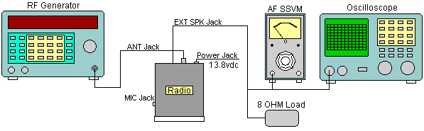
CONNECTION
ADJUST FOR
1.
Channel:
19
Clarifier center
Volume fully clockwise
RF GAIN fully clockwise
Squelch fully counter clockwise
NB/ANL : off Mode AM
2
Same as step 1
L11,
L10,
L8, L7,
L6 L5,
L4, and L3
Then adjust coils for maximum reading on AF SSVM. Repeat this step reducing the SG output.
3
Same as step 1
L3
Adjust for max. reading on AF SSVM, Check the sensitivity difference between CH1 and 40. If it is over 1 dB, re-adjust L3 to obtain within 1 dB.
4
Same
as step 1
except squelch is fully clockwise.
VR2
Then adjust so that the AF signal will just appear on Oscilloscope.
5.
Same as step 1
VR1
Then adjust for "S-9" reading on Transceiver's meter.
6
Same
as step 1
except NB/ANL switch is ON.
L2
Adjust the level of SG to approx. 1.6uV. Then adjust for max. DC reading.