STEP
SETTINGS
CONNECTION
ADJUST FOR
1
CH:
40,
AM, RX
Clarifier in center
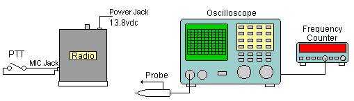
Connect scope to TP2
Adjust
for 4.5V DC reading on Oscilloscope.
(Oscilloscope in DC mode)
2
Same
as step 1.
CH: 1.
Connect scope to TP2
Check that the voltage is more than 2V DC on Oscilloscope.
3
Same
as step 1.
CH:19
USB, RX
Connect scope to TP3
Adjust for maximum reading on Oscilloscope.
4
Same as step 3.
Connect Frequency counter to TP3
Adjust for 16.4925 MHz ±20 Hz.
5
Same
as step 1.
CH: 19
AM, RX
Same as step 4.
Adjust for 16.4900 MHz ±20 Hz.
6.
Same
as step 1
CH: 19
LSB, RX.
Same as step 5.
Adjust for 16.4875 MHz ±20 Hz.
7.
Same
as step 1
CH: 19
LSB, TX
Same as step 6.
Adjust fur 16.4875 MHz ±20 Hz.
8.
Same
as step 1.
CH: 19
LSB, RX
Connect Frequency counterTP5
Adjust for 10.6925 MHz ±20 Hz.
9.
Same
as step 1
CH: 19
USB, RX
Same as step 8
Adjust for 10.6975 MHz ±20 Hz.
10.
Same
as step 1.
CH: 19,
TX, AM.
Disconnect TP6, TP7, TP8
Connect Frequency counter TP9
Adjust for 10.6950 MHz ±5 Hz.