Galaxy
DX Radios
Documentation Project
CBTricks.com
Galaxy
DX Radios EPT360014B and EPT360014C Notes:
|
In doing this I have
made a few notes you may find of interest.
I have seen 3 different silk screens used on the EPT3600-14B (main PCB).
They have the following markings KAI HWA2-002 V0, SM YGOI
94 V0, M-294 HB-C
There
will be updates to this section as I get along wth this project, so check
back.
|
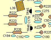 PCB Grid Location B1
 |
TR45 silk screen shows
the flat to the left on all silk screens used.
If a 2SC1973 is installed in the location the flat is to the left.
If a 2SC2538 is installed in this location the flat is to the right.
All the board layouts
on this site will show TR45 flat is to the right.
|
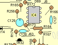
 PCB Grid Location C5
 |
There is two places
marked TR30 on the following silk screens KAI HWA2-002 V0, SM
YGOI 94 V0.
The Transistor in
grid location C5 is TR39 TR30 is at Grid Location E4. The layout drawing
on this site has TR39 labeled as TR39.
Note that on the M-294
HB-C PCB silk screen TR39 is marked as TR39
|
 Grid Location D6 &
E6
Grid Location D6 &
E6 |
C128 and C129 are
swapped on the factory schematics (aka Tube schematics set) on some radios
but not all. On all the layouts on this site C128 and C129 will be as
the drawing to the left and this also this is also the way all versions
of the silk screens used are. And the schematics on the site will be changed.
Tube schematics errors
On the following schematics the part labels are swapped the part value's
are right.
DX77HML, DX88HL, DX99V
On the following schematics
the part labels are NOT swapped.
DX55V, DX66V, DX73V
|
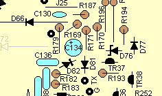 Gride Location E6
 |
On the KAI HWA2-002
V0, SM YGOI 94 V0 boards C130 silk screen label is closest
to the front.
On the M-294 HB-C PCB C136 silk screen label is closest to the front.
Also these parts are
swaped on the factory schematics (aka Tube schematics set) on some radios
but not all.
On the following schematics
the part labels are swapped the part value's are right.
DX55V, DX66V, DX73V
On the following schematics
the part labels are NOT swapped.
DX77HML, DX88HL, DX99V
All the board layouts on this site will show C136 closest to the front
and the schematics on this site will be change to show this.
|
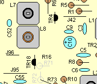 Grid Location C2
 |
The silk screen on
all PCB's shows the flat of TR18 to the left.
With a J310 installed
in this location the flat is to the right as shown on all layouts on this
site.
|
|
The following applies
to all PCB's
(a)
There are two places marked R140. The layout drawing and parts list
shows these
as
R140A at grid location E3 and R140 at grid Location F3.
(b) There
are two places marked R275. The layout drawing and parts list shows
these as
R275
at grid Location F2 and R275A at grid Location E4.
(c) There
are two places marked D94. The layout drawing and parts list shows
these as
D94
at grid location D1 and D94A at grid location F3.
(d)
There are two places marked L50. The layout drawing and parts list
shows these as
L50
at grid location E2 and L50A at grid location A2.
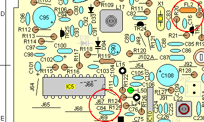
(e)
There are two places marked C84. The layout drawing and parts list
shows these as
C84
at grid location E2 and FL2 at grid location D2.
(f)
There are two places marked J102. The layout drawing and parts list
shows these as
J102A
at grid location D2 and J102 at grid location F3.
(g)
There are two places marked C84. The layout drawing and parts list
shows these as
C84
at grid location E2 and FL2 at grid location D2.
|
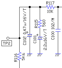 |
Factory schematics
(Tube schematics set) there is an error on C101 and R115. The schematics
show R115 to ground, but in fact C101 is on the ground side of R115 as
shown in the diagran on the left.
|
DX33 - In
current production C170 is not in the radio and should not be on the schematic.
In early production C170 was installed on the solder side of the main pcb and
the value was 100pf.
DX44 - In
current production C170 is not in the radio and should not be on the schematic.
In early production C170 was installed on the solder side of the main pcb and
the value was 100pf.
DX55 - In
current production C170 is not in the radio and should not be on the schematic.
In early production C170 is not in the radio and should not be on the schematic.
DX66 - In
current production C170 is not in the radio and should not be on the schematic.
In early production C170 is not in the radio and should not be on the schematic.
DX73 - C170
was installed on the solder side of the main pcb and the value was 150pf.
This model is discontinued so all or most of them had C170 installed.
Copyright
© 2002, 2003, 2004 CBTricks.com
Disclaimer:
Although the greatest care has been taken while compiling these documents,
we
cannot guarantee that the instructions will work on every radio presented.