|
RADIO
MODIFICATIONS
Frequency
Conversion
For
(EPT004410Z Band PCB)
Frequency
Conversion For (EPT004410A "SMT" Band PCB)
Channel
Chart (After Modification)
10
meter FM Mod (28.000 - 29.655MHz)
Clarifier
Mod
Disabling
Talkback
("SMT"
Echo PCB) ( EPTOSSB50C)
Disabling
Talkback
(EPTOSSB50B) (Used in Early DX99V's)
Roger
Beep Tone Mod
ALIGNMENT
PROCEDURES
PLL
Alignment
Transmitter
Alignment
Receiver
Alignment
Alignment Locations
VCO Frequency Generation Chart Bands Bands
A-D and Bands E-H
SEMICONDUCTOR
INFORMATION
Transistor
Voltage Chart
Integrated
Circuits Voltage Chart
Semiconductor
Datasheets
DIAGRAMS
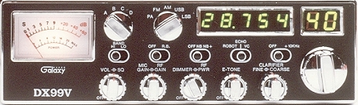
DX99V
Block Diagram
DX99V Schematic
Diagram (old)  (Early
DX99V) (Oct. 29, 1993) (Early
DX99V) (Oct. 29, 1993)
DX99V Schematic
Diagram (current production)
(Feb. 27, 2004)
Active
Device Location Diagram (Main Board)
Band
Board Schematic Diagram (EPT004410Z)
Dimmer
PCB Schematic Diagram (EPT55V-51Z)
Frequency
Counter PCB Schematic Diagram (EPT210014C)
Frequency
Counter PCB Schematic Diagram
(EPT210014D)
ROBOT
PCB (EPT055V60Z)  (Used in Early DX99V's)
DX99V
Inter-connection Diagram
DX99V
Inter-connection Diagram
Echo
/ Voice Changer/Robot Schematic
( EPTOSSB50C )
PCB Layouts and
Parts
Main
PCB (EPT360014B)
Mode Switch PCB
(EPT066V40Z)
Band Board Layout
PCB (EPT004410Z)
Band Board Layout
SMT (EPT004410A) Later Production
Channel Selector
PCB (EPT055V30Z)
Frequency Counter
Board Layout (EPT210014C)
Frequency
Counter PCB (EPT210014D) (Started with later 2005 Production)
Mic Jack PCB
(EPT360050Z)
Dimmer
PCB (EPT55V-51Z)
Display PCB
(EPT055V20Z)
Echo PCB
Layout (EPTOSSB50B) (Used in Early DX99V's)
ROBOT PCB
(EPT055V60Z) (Used in Early DX99V's)
Echo / Voice
Changer/Robot PCB ( EPTOSSB50C) (Used for about last 12 years)
Chassis, Miscellaneous
& Mechanical Parts
Front
View Chassis Parts
Front
View Chassis Parts
Rear
View Chassis Parts
Rear
View Chassis Parts
Miscellaneous
& Mechanical Parts
Stock
Mic Wiring Diagram
|
Stock
1- Shield
(Ground)
2- Yellow (Audio)
3- Red (Transmit)
4- White (Receive)
Astatic (4
wire)
1- Shield
2- White
3- Red
4- Black
Astatic (6
wire)
1- Shield & Blue
2- White
3- Red
4- Black
Yellow NC
Daiwa EM-500
Cobra CA Series
1- Shield & Black
2- Red
3- White
4- Blue
Galaxy DC-521S
(4 wire)
1- Shield
2- Yellow
3- Red
4- Black
Galaxy CB-660EI
1- Shield & Black
2- White
3- Red
4- Blue
Sadelta
1- Shield
2- White
3- Brown
4- Green
Turner
1- Shield & Red
2- White
3- Blue
4- Black
Yellow NC
|
