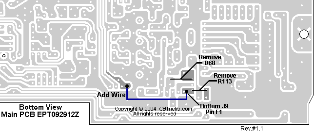
Looking at the front edge of the main PCB on the copper side .
Remove D68 and R113 then run a wire from the bottom of J9 as shown above.
You should now have 1khz down & 1khz up slide on transmit from center slot
Galaxy
DX Radios DX979
Documentation Project
CBTricks.com
Clarifier
Mod
|
NOTE: If
you have even the slightest doubts or the proper equipment , it would
be wise to have someone else you trust perform the mod for you. |
 |
|
Looking at the front edge of the main PCB on the copper side . Remove D68 and R113 then run a wire from the bottom of J9 as shown above. You should now have 1khz down & 1khz up slide on transmit from center slot |
| SETTINGS | CONNECTION |
ADJUST
|
ADJUST FOR |
|
VCO: |
Connect Multi-meter
to TP2. |
L14
L15 VC1 |
2.5
VDC ± 0.1 Adjust for 2.6 VDC ± 0.1 Adjust for max. 10.2400MHz ± 20Hz |
| AM Frequency: Set radio to CH 19 AM RX mode. |
Connect Frequency Counter to TP3. |
L20
|
16.4900MHz ± 20Hz |
| USB
Freq: Set radio to CH 19 USB RX mode. |
Connect frequency counter to TP3. |
L21 |
16.4925MHz ± 20Hz |
| LSB Freq: Set radio to CH 19 LSB RX mode. |
Connect frequency counter to TP3. |
L22
|
16.4875MHz ± 20Hz |
Disclaimer: Although the greatest care has been taken while compiling these documents,
we cannot guarantee that the instructions will work on every radio presented.