 |
RADIO
MODIFICATIONS
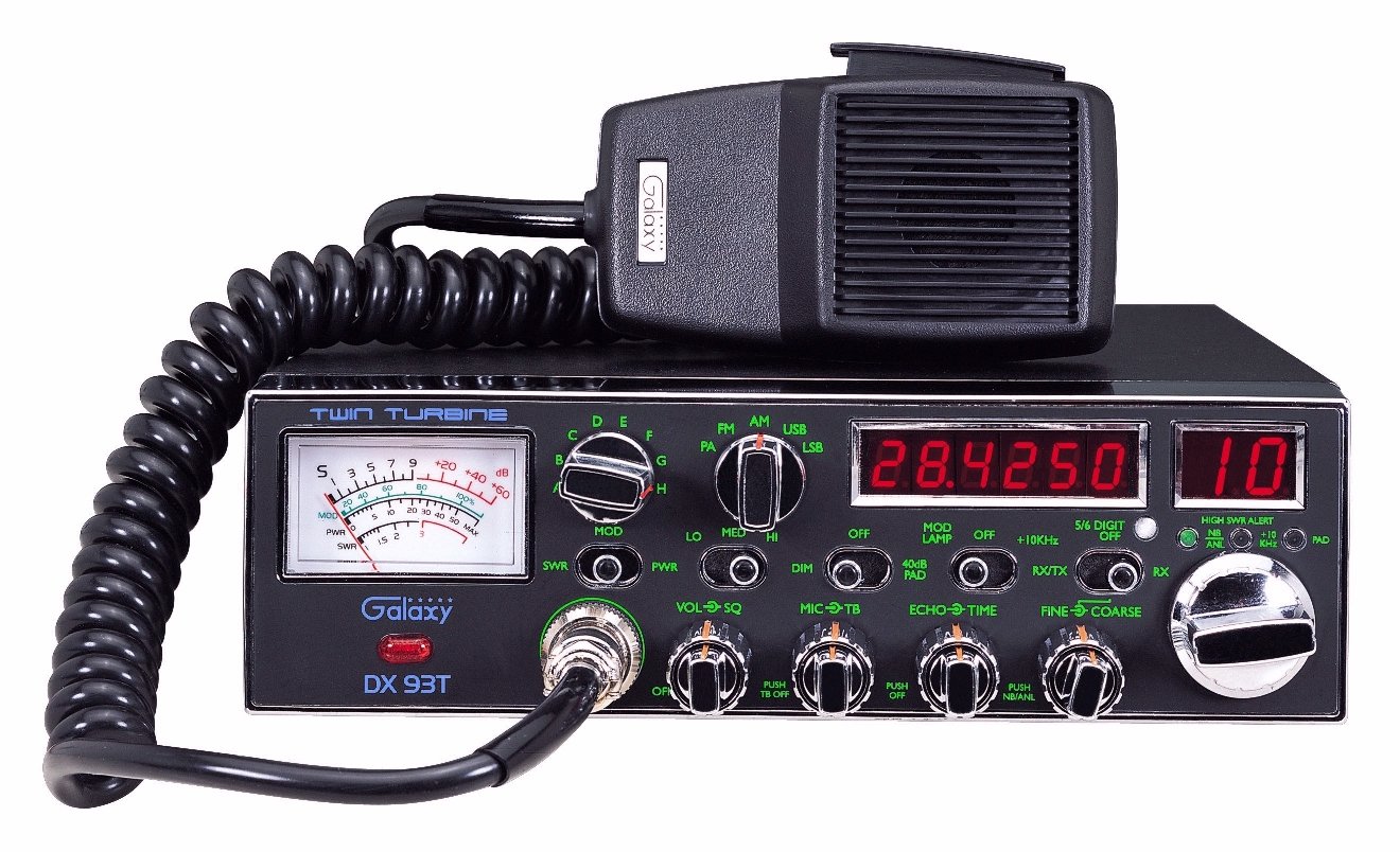
DX93T
Frequency Conversion
Channel
Chart (After Modification)
Extended
10-Meter Frequency Conversion (28.000 - 29.655MHz)
ALIGNMENT
PROCEDURES
PLL Alignment
Transmitter Alignment
Receiver Alignment
Alignment Locations
VR
PCB Alignment Locations
SEMICONDUCTOR
INFORMATION
Semiconductor
Datasheets
DIAGRAMS
Schematic
Diagram Main  (July 19, 2001)
RF Amp
Schematic (EPAC05010B)
EL
Driver Schematic (EPT91V130Z)
ECHO
PCB Schematic (EPT0SSB51J)
Control
wiring
(Feb. 28, 2001)
Control
wiring
(Nov. 07, 2005) (Blue LED version see Note below)
DX93T
Chassis Inter-connection Diagram
DX93T
Chassis Inter-connection Diagram 
PCB Layouts and
Parts
Main PCB Layout
(EPT690010Z) (EPT690010C)
VCO
PCB (EPF000210Z)
RF AMP PCB
(EPAC05010B)
Dimmer PCB
(EPT091V40A) Early Production
Dimmer PCB
(EPT091V41A) Current Production
EL Driver
PCB (EPT91V130Z)
ECHO PCB (EPT0SSB51J)
VR PCB (EPT091V91Z)
Display / Switch
PCB (EPT091V21Z) (See Note: Below)
Channel Selector
/Frequency Counter PCB (EPT091V31Z)
Channel Selector
/Frequency Counter PCB (EPT091V30A) (See Note: Below)
SWR
PCB (EPT360042Z)
MOD LED PCB
(EPT91V100Z)
LED PCB
(EPT91V120Z)
Note: The
last production run of this model had blue LED's and the Clannel Sel.
PCB was changed to EPT091V30A)
Chassis, Miscellaneous
& Mechanical Parts
Chassis
& Mechanical Parts
Mic Wiring Diagram
|
Stock
1- Shield
(Ground)
2- Yellow (Audio)
3- Red (Transmit)
4- White (Receive)
Astatic (4
wire)
1- Shield
2- White
3- Red
4- Black
Astatic (6
wire)
1- Shield & Blue
2- White
3- Red
4- Black
Yellow NC
Daiwa EM-500
Cobra CA Series
1- Shield & Black
2- Red
3- White
4- Blue
Galaxy DC-521S
(4 wire)
1- Shield
2- Yellow
3- Red
4- Black
Galaxy CB-660EI
1- Shield & Black
2- White
3- Red
4- Blue
Sadelta
1- Shield
2- White
3- Brown
4- Green
Turner
1- Shield & Red
2- White
3- Blue
4- Black
Yellow NC
|