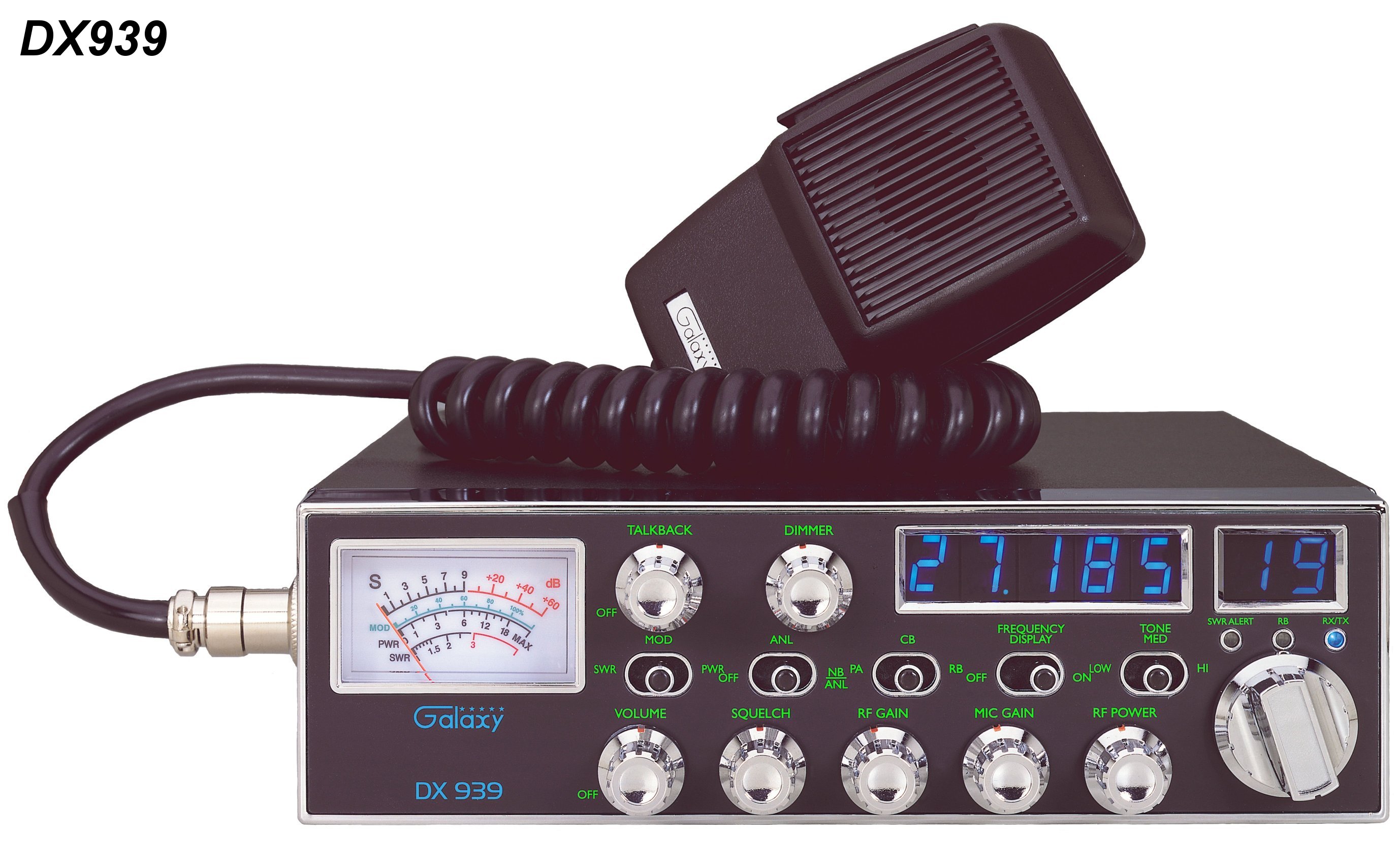
Galaxy DX Radios DX939
Documentation Project

CBTricks.com

TIPS:
You need to have Acrobat Reader version 5 or newer installed to view the files with icon.

If the files with or icon will not display see the Site FAQ for help on printing, viewing and using this information.

SPECIFICATIONS
      Owner's Manual


Click to see full size


RADIO MODIFICATIONS
      Frequency Conversion
      Channel Chart (After Modification)

ALIGNMENT PROCEDURES
     PLL Alignment
     Transmitter Alignment
     Receiver Alignment
     Alignment Locations

SEMICONDUCTOR INFORMATION
      Semiconductor Datasheets

DIAGRAMS
    DX939 Schematic Diagram (EPT069611A) (Oct. 15, 2007)
    Chassis Exploded View

PCB Layouts and Parts
    Main PCB (EPT069611A)
    Channel Selector PCB (EPT099N20Z)
    Display PCB (EPT073N30Z)
    VR PCB RF Power / VOL / SQ MIC Gain / RF Gain (EPT093940Z)
    VR PCB Dimmer/ Talkback PCB (EPT093950Z)
    Dimmer PCB (EPT091V40D)
    EL Driver PCB (EPT91V131Z)
    Slide Switch PCB (EPT093930Z)
    Frequency Counter PCB (EPT900043Z)
    Modular 002 VCO PCB (EPF000210Z)
    Modular 005 PCB (EPT613010Z)
    MIC PCB (EPT690050Z)
    SWR PCB (EPT360042Z)

Chassis, Miscellaneous & Mechanical Parts
    Miscellaneous & Mechanical Parts

Mic Wiring Diagram

Stock
1- Shield  (Ground)
2- Yellow  (Audio)
3- Red      (Transmit)
4- White   (Receive)

Astatic (4 wire)
1- Shield
2- White
3- Red
4- Black

Astatic (6 wire)
1- Shield & Blue
2- White
3- Red
4- Black
Yellow NC

Daiwa EM-500
Cobra CA Series

1- Shield & Black
2- Red
3- White
4- Blue

Galaxy DC-521S (4 wire)
1- Shield
2- Yellow
3- Red
4- Black

Galaxy CB-660EI
1- Shield & Black
2- White
3- Red
4- Blue

Sadelta
1- Shield
2- White
3- Brown
4- Green

Turner
1- Shield & Red
2- White
3- Blue
4- Black
Yellow NC


Copyright © 2007 CBTricks.com

Disclaimer: Although the greatest care has been taken while compiling these documents,

we cannot guarantee that the instructions will work on every radio presented.