Galaxy
DX Radios DX11B
Documentation Project
CBTricks.com
Frequency Conversion

Export Frequency Conversion
|
1.
|
Remove
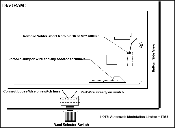
the bottom cover of the unit and locate the row of 15 pins along the front
edge of the board. Unsolder the wire connected to one of these pins and
remove it. Make sure that no other pins are shorted together in this row. |
|
2.
|
Locate
the loose wire (usually Purple) in the wiring harness and solder it to
the terminal to the left of the Red Wire. Notice that there are two buss
wires that connect several terminals together, the Red wire connects to
the right side, and the loose wire (Purple) will be soldered to the left
side. |
|
3.
|
Locate the MC14008 IC on the circuit board as shown in the diagram above. Unsolder the small solder bridge between pin 16 and the upward extending trace. Be carefull not to short any other pins and make sure that pin 16 is properly soldered to the board. These chips are very static sensitive so if your channels skip around erratically, changing this chip will most likely solve it. |
WARNING! Not Legal For Class D CB Use In The U.S.A.
Disclaimer: Although the greatest care has been taken while compiling these documents,
we cannot guarantee that the instructions will work on every radio presented.