If you are interested in monitoring static levels around you in stormy weather, this circuit will be an easy way to get started. Since I was young I was always interested in such things, like the RF noise the Earth produces, as well as RF from storm activity. I also thought that since I had other antennas in the air if I could detect a strong field building up around me I would have some advance warning that lightning might be a danger. In one circuit I used a comparator to activate a sonalert if the field in volts/meter reached a preset value.
| I have built many types ranging from tube circuits to dual gate mosfet, etc., but the circuit shown has proven to be very reliable and useful in such activities. If you cannot find a zero center meter I am sure you can easily adapt single ended types, as well as altering the circuit values for varying meter impedance and current ranges. You can use many types of fets here, although in this circuit I chose a P channel jfet. A single ended circuit can also be built simply using the fet current to drive a static meter, just be sure to connect the gate load resistance to positive with a P type fet and negative with an N type. |
THE CIRCUIT
 | In the circuit shown the gate of the P jfet is tied to ground since a dual polarity supply is used, through a very high resistance, in my first one I used 11,000 megs. Keep in mind that not only are these very hard to find you will also notice that it is a moot point if there is too much leakage in your circuit. In that light it is best to standoff the gate and use a high quality new coax to your outside antenna, usually a capacitive hat type. You must also come up with a mount design which keeps rain from the point on the mount where current could flow to ground, or you will notice that your meter becomes very insensitive as it starts raining. |
I used a 22 inch shaft from a Wilson antenna in a regular mobile antenna mount, with 2 nuts on top to hold the capacitive hat and a plastic umbrella to protect the mount from moisture.
| Likewise the coax connection must be well sealed from moisture, and here I used N type connectors at the antenna and on the chassis for the meter inside my house. As far as the resistance load goes I am sure you can hombuild a high value type if need be, for the strong field load I used a 10 meg potentiometer which I could switch out of circuit. For the switch here I used a ceramic high voltage type to minimize leakage, but You will find that cheaper types work very well in this circuit. The fet type is not critical, I used the J176 from All Electronics, also the meter and 10 meg pot came from them as well. |  |
As far a a power supply is concerned the 12 volts for the audio is not critical, but the dual polarity should be very well regulated and preferably from a different transformer or winding if a line supply is built, as current surges from the audio IC will unbalance your meter circuit.
Through experimentation I found that controlling the offset of an op amp gave a very sensitive way to control meter balance, far superior to trying to shift the meter itself. I might add here that if you cannot find a zero center meter you might ground the end, or put it on a trimmer tap where the ends of the pot are on the plus and minus of the supply, say a 5 or 10 K pot. I tried this and it worked ok but I like the 250-0-250 uA meter better than other circuits I have built. I have yet to produce a good circuit design that would auto zero the meter, usually I find that it takes away from the polarity reversal information you will see in lightning discharges, as well as polarity reversals in the field around you. In the maximum gain mode you can notice field gradient changes in clear weather from morning to night, as well as detect storms more than a state away. One problem you will notice with this circuit especially at high gain settings is that you have to re-zero the meter often as the polarity changes overhead in stormy weather.
 | 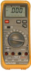 DVM 345 Velleman Digital Multimeter | Analogic meter can be replaced by digital multimeter with PC interface also. In the picture beside an example of the Digital Multimeter Velleman DVM345, used like transient recorder. The software shows the graphics of values and stores the collected value in a ".dat" file. | |||
| MasView software for Windows by Velleman (www.velleman.be) | with PC interface |
The higher the gain of the op amp or the higher the input impedance of the fet gate the more this is a problem, which is why I added a way in strong fields to lower the impedance of the gate circuit and reduce the op amp gain as well. I also provided for audio to be taken from the op amp, and mixed with separate levels for the static and RF signals, as well as a master volume.
AUDIO SECTION
The audio is from a simple LM380 IC circuit, you will notice interaction between controls here if you build it as shown. A buffer and mixer circuit would be helpful here, but I was trying to keep the parts count low in this design. Also, an equalizer circuit for the signal out is a very good addition, so you can tailor the output response and reduce unwanted signals such as line power noise.
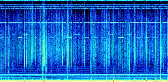
In the picture an example of audio signal output 0-22kHz (obtained by Spectrum Lab Software by DL4YHF).
From bottom to top: hum noise, spherics, Alpha stations, one CW and many RTTY signals.
RF SECTION
For the RF section I used an old low frequency tesla coil I built on a 4 foot long 6 inch diameter pvc pipe, where I wound about 3,000 turns on it. You will find that just a straight whip antenna works well here, as well as lumped components, so the monster coil is not mandatory, I just wanted a lot of signal at low frequencies with a high Q inductor, to give more signal while trying to reduce the overall gain of the circuit, to minimize 60 cycle hum. On that note long whips or especially long wires are not very desirable here. The signal is amplified with a jfet input op amp, with selectable input range through a small value capacitor to allow high gain to be achieved with minimum 60 cycle hum. A 741 op amp gives gain to provide audio signal and then another 741 is used to drive a 500 ua single ended meter for a reading of RF levels. I find it helpful to make the series resistance control for the meter to be a front mounted control as well as the gain control for the meter driver 741, as it give much more flexibility under differing weather conditions. This meter is very helpful in determining the number of lightning strokes per unit time in severe weather.
CONCLUSIONS
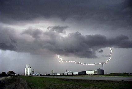
 | I have noticed in stormy weather that such things as large energy releases inside the clouds will be followed by sudden downpours, indicating that the fields inside the clouds were holding large amounts of water, and when a cloud sees a sudden loss of large amounts of electrical energy the water is no longer held, with the result of rain coming down in buckets after strong discharges. Pretty much this is common sense, many years ago while reading some notes by Nikole Tesla on this subject I was interested in this effect, and I find that it is interesting to actually watch the energy build up in the clouds and then be released with the resultant torrent coming soon after. |
Russell Clift AB7IF Copyright 2001 Russell E. Clift