
Coax
Theory
by Russell E. Clift, AB7IF
Having over
the years heard so many differing reasons for what is going on in a coax, concerning
SWR, reflections, and other things; I decided to have a short discussion of
what is occurring in the line. Here I use a DC voltage, which gets the point
across just fine even if we are dealing with RF. In this case I use 50 ohm coax,
and assume it takes one microsecond for a voltage wave to travel from end to
end from t=o, the moment the switch is closed. I will use the drawing below,
first for an open line and second for a shorted (at the output end) line. While
I am not an artist, I hope the drawing is ok. We can use lumped components for
the coax, in this case I will use 3 sections.
Also, I inserted a 50 ohm resistor in series with the 50 ohm line, to make the
numbers easier to be understood. Or at least easier to explain. Note that incident
and reflected waves are traveling waves.
 |
 |
(Click on each picture to enlarge the image)
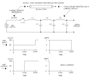
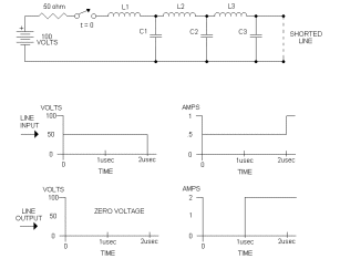
OPEN LINE: When the switch is closed at t=0, 1 amp will flow from the 100 volt source, since the 50 ohm resistor is in series with the 50 ohm impedance of the line, (the resistor is added so the applied voltage to the line will be 50 volts). As the capacitors begin to charge one by one, a voltage wave moves down the line, which we call the incident voltage wave. There is also an incident current wave which propagates with the incident voltage wave. In 1 usec when the incident waves reach the end of the line, and C3 is charged to 50 volts by the current through L3, and there is no more coax to charge so the magnetic field around L3 will collapse, and the collapsing field will keep the current flowing in C3 in the same direction, charging C3 to 100 volts. Since the current in L3 is now gone, the current in L2 collapses, and in the same way charges C2 to 100 volts as well. Likewise now L1's field collapse charges C1 to 100 volts, until the voltage all across the line is 100 volts, and current flow in the line is zero. The source at this time (t=2 microseconds) "sees" an open circuit for the line. The capacitors charging from 50 volts to 100 volts from the end of the line toward the source creates a reflected voltage wave traveling toward the source propagating in phase and in the opposite direction of the incident voltage wave. The inductors, discharging from the open circuit toward the source create a reflected current wave propagating out of phase and in the opposite direction of the incident current wave. In the drawing are shown the voltage and current verses time at both the input and output ends of the line.SHORTED LINE: The line charges in the same way as the previous circuit but since the voltage must equal zero in a short circuit, when the incident voltage and current waves reach the short circuit (in 1 usec), the charge on C2 must discharge into L3, producing a current of 2 amps in L3. When the voltage of C2 approaches zero, C1 discharges into L2, producing 2 amps of current in it. This goes on until the entire line is at zero volts. The reflected current wave in this case is in phase with the incident current wave, while the voltage reflection in this case is out of phase with the incident voltage wave. At t=2 usec, the source "sees" a shorted line.
The differences for open
and shorted lines are:
(1.) The voltage reflection from an open circuit is in phase, and from a shorted
line is out of phase with the incident wave.
(2.) The current reflection from an open circuit is out of phase, from a shorted
line it is in phase.
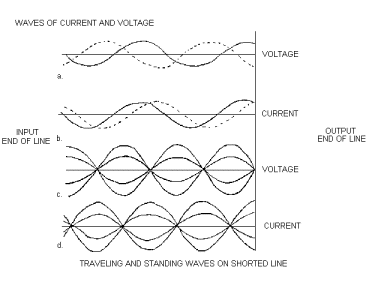
When a transmission line is terminated in it's characteristic impedance there is no voltage or current reflection from the line. The electromagnetic fields continue to flow into the termination as if the line were infinitely long. When a mismatch of impedance occurs, reflected waves will be produced and they will interact with the incident waves. The total voltage and current on the line are no longer the result of a single travelling wave from the source to the load. Instead, it is the algebraic sum of two waves travelling in opposite directions. This interaction results in what is known as standing waves. The waves remain in fixed positions along the line while they vary in amplitude and polarity. A wave of any shape can be transmitted along the line without any change of waveshape or magnitude. Looking at the gif below, we see a line driven with a sine wave generator, terminated with a short circuit to maximize the reflection.
 |
 |
(Click on each picture to enlarge the image)
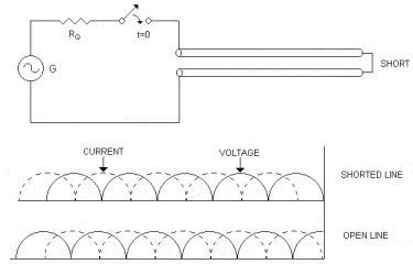
In the the gif on the right the incident waves of current and voltage are shown in a and b, while the standing waves of current and voltage are shown in c and d. In the first jpeg, looking at the waveforms below the circuit, we see a simpler way to visualize the standing waves, by ignoring the polarity and only seeing the magnitude of the waves. This is exactly what an RMS meter would show at each point along the line we measured. The points of zero voltage are called nodes or voltage nodes, while points of maximum voltage are called loops or antinodes. The position of the generator from the load will determine the type of impedance the generator "sees". This is the very cause of so much confusion as to what differing coax lengths do to SWR, or at least what is "seen" as the SWR at the point of meter insertion. I have heard it stated many times by others that the line length does not affect the SWR, but this can only be possible when there is ZERO reflection of energy, a perfect match, something which never happens in the real world. The reason I use a shorted line here is to create maximum reflection to show clearly what is going on. With a termination closer to the line's impedance the resulting reflections would be weaker in amplitude as compared to the incident waves, and the algebraic sum in the standing waves would contain a correspondingly smaller component of reflection amplitude or energy. Normally we want the generator to be at a voltage or current loop, depending upon what we were trying to do. As an example we would want half wave multiples between source and load for a single antenna, and quarter wave or odd multiple's of quarter waves for a dual antenna installation. keep in mind that an antenna is really 36 ohms not 50; so the 14.1 feet of half wave shows 36 ohms towards the radio, and the missing 14 ohms is added by the remaing 3.9 feet of coax in an 18 foot single. This gives us 50 ohms roughly at the radio end and is just exactly why antenna manufacturers spec out 18 feet for the coax run to their antenna's. When a transmission line has standing waves on it the dynamic impedance of the line is no longer equal to the characteristic impedance of the line, unlike the example of only incident travelling waves without any reflections occuring. The reflected waves will alter the input impedance that the generator (your boat anchor radio) "sees".
Going back to the first image, looking at the waveforms below the circuit we see that standing waves go from maximum to minimum in 1/4 wavelength intervals along the line. The open or short circuited line will present to it's source a high or low impedance at multiples of 1/4 wavelength, depending upon the location of the source in reference to the load (an effect you see when you alter coax lengths). At points that are not an exact 1/4 wavelength multiple from the load or antenna, the line acts as a capacitor or an inductor. Current at the generator will either lead or lag the voltage. An open or short circuited line may assume the characteristics of a resonant circuit formed of lumped component elements of inductance and capacitance.

Looking at the last picture we see first an open line and second a shorted line. In either case we see a resistive line at 1/4 wave multiples from the load. Importantly, we see an image of the load impedance every even number of 1/4 waves (1/2 waves), and an inverted or mirrored image at every odd 1/4 wave multiple (back to our dual harness again, in theory we get two 100 ohm or nearly so resistors in parallel letting the radio "see" 50 ohms), and at any other point on the line we see a range of complex impedance which contains inductive or capacitive reactance. This effect is often used to "match" a load/line combination to a generator. In other words, if we have a mismatch between the load (antenna) and the line creating standing waves, then we can use a specific line length to make the generator "see" a good match or SWR. This is the most misunderstood and argued about effect in radio among CB'ers, and we can see from the pictures and explanation not only what is really going on once and for all, but we can also see how to take advantage of these facts to make an antenna system perform as well as is possible, given the particulars involved in any installation. Also, looking at the shorted line picture at each odd 1/4 wave multiple we can see that excepting losses the line appears to vanish to the circuit. What can we use this for you may ask (assuming like me you don't have a life so you actually think about these things); if we take a 1/4 wave line and put a pl 259 on one end, and short the other end, we make a nice trap. Putting a T at the antenna, we connect the shorted 1/4 wave. Now at any frequency other than the resonant frequency of the line, we see a short circuit. We also see a DC short circuit. So we have not only protected our system from static build up and nearby lightning transients, we also have made a very high quality harmonic filter to help keep us out of the neighbors television, one with superior characteristics to a lumped component type of filter, far lower loss due to dissipation, and power handling capability equal to the coax used. As a side benefit, we have also added another radial or counterpoise to the antenna system which helps to improve the overall RF ground and lower the SWR of the system, all while increasing radiation efficiency. This can also be used in a mobile linear installation, as I have done for many years.